Robot FANUC SR-12iA optimization project thumbnail
Back to projects
Automation/FANUC / Roboguide / Cycle Time / Maintenance

Cycle Time and Wear Optimization of the FANUC SR-12iA Robot

Cycle Time and mechanical wear optimization of the FANUC SR-12iA (SCARA) robot in a simulated pick-and-place operation using iRVision. Finding the perfect balance between production efficiency and fault-free operation time.

Project Assumptions

The analysis was conducted for a robotic cell designed to pick and place randomly oriented parts (positioned by the iRVision system). The weight of the tool (gripper) is 0.3 kg, and the weight of the picked part (connecting rod) is 0.2 kg (total actual robot payload is 0.5 kg).

The work cycle includes a 3-second wait for the part to reach the picking zone and a 1-second delay for startup and signal exchange.

The simulation configuration assumes the tested robot cycle runs for 20 hours a day and 300 days a year, with thermal load calculated for an ambient temperature of 20°C.

The simulation objective is to find the optimal solution for arranging 10 connecting rods within a maximum time of 20 s.

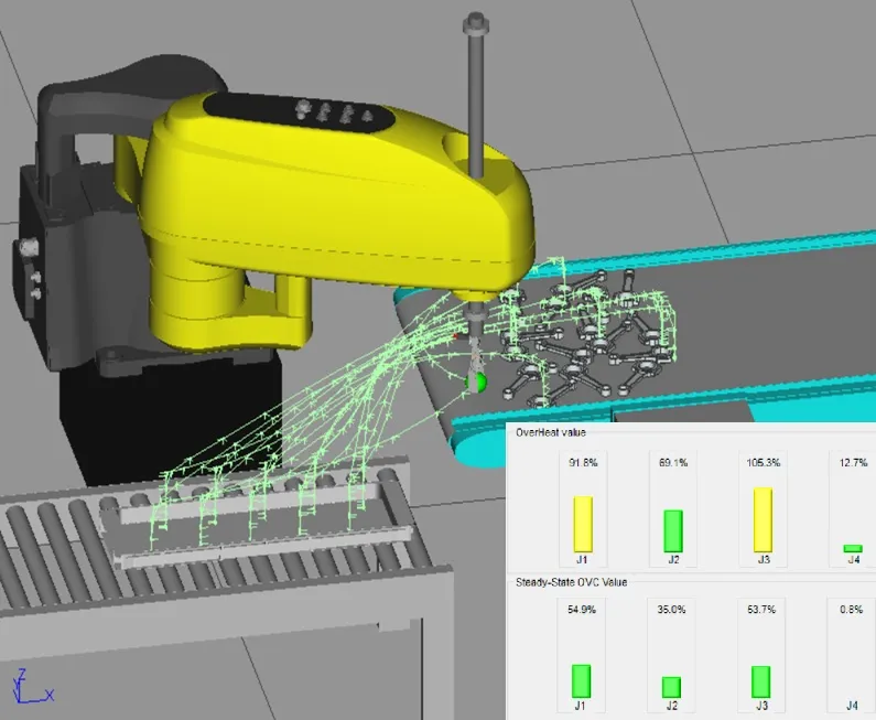
Direct robot movement between points (best time)

Summary

Specific configuration changes affect the robot's performance parameters as follows:

  • Overestimating the declared mass (e.g., from 0.5 kg to 1.0 kg):
    • 🔴 Negative effect: The controller automatically limits the machine's dynamics, unnecessarily extending the cycle time.
    • 🔴 Negative effect: No improvement in equipment lifespan (absolutely no benefits).
  • Lower speed (e.g., changing from 100% to 80%):
    • 🟢 Positive effect: Significant increase in gear lifespan and lower thermal load on motors.
    • 🔴 Negative effect: Longer cycle time (loss of about 2 seconds).
  • Movement via an intermediate point (arm folding):
    • 🟢 Positive effect: Reduction in the moment of inertia and lower load on the main reducer (J1).
    • 🔴 Negative effect: Extension of cycle time.
  • Linear Movement (L):
    • 🟢 Positive effect: Traveling the shortest path (straight line) ensures a shorter cycle time.
    • 🔴 Negative effect: Leads to higher thermal overloads on the robot's axes.
  • Joint Movement (J):
    • 🟢 Positive effect: Smooth motor operation, even load distribution, and safe temperatures.
    • 🔴 Negative effect: Moving along an arc extends the cycle time.

2. Variable Analysis and Motion Physics

The most heavily loaded mechanical component in the FANUC SR-12iA robot is the main axis reducer (Axis J1). The lifespan of the second axis reducer (Axis J2) easily exceeds the standard 8 years in all tests. The vertical and rotary axes (J3 and J4) do not have traditional reducers subject to mechanical wear, but the J3 axis is sensitive to thermal overloads.

  • Payload Issue: Entering an overestimated mass into the controller is a mistake. The controller reduces acceleration, which extends the cycle, but does not decrease the physical forces acting on the gear. The correct mass (gripper + object) should be used to unlock full performance.

  • Impact of Robot Speed: Reducing the speed by just 20% (from 100% to 80%) drastically reduces kinetic energy during braking. Accepting a cycle extension of about 2 seconds extends the J1 reducer lifespan from 1.5 years to over 5 years.

  • Interpolation Type (Joint vs Linear): Linear movement (L) guides the tool in a straight line, which shortens the cycle but requires more motor effort (overuse overheats axis J3). Joint movement (J) allows the motors to take the path of "least resistance" - which is not a straight line. This ensures smooth and stable operation without overloading the system.

  • Impact of Trajectory and Moment of Inertia: Direct travel involves moving with a fully extended arm - motor J1 must generate massive torque to brake the mass (gear degradation). An intermediate point forces the arm to fold, which drastically reduces inertia and relieves the J1 gear, although it extends the cycle time.

Robot movement from pick to place point via an intermediate point.

Table - summary of tested configurations, cycle time and wear:

No. Configuration Cycle Time [s] J1 Lifespan [years] J1 Overheat [%] J2 Overheat [%] J3 Overheat [%] J4 Overheat [%]
1 Speed 100%, payload 0.5kg, L motion, direct movement 17.23 1.2 91.8 69.1 105.3 12.7
2 Speed 100%, payload 1.0kg, L motion, via intermediate point 17.58 1.7 91.3 80.8 114.2 17.0
3 Speed 100%, payload 0.5kg, L motion, via intermediate point 17.88 1.8 90.3 79.2 111.7 17.0
4 Speed 100%, payload 1.0kg, J motion, direct movement 17.94 1.4 87.3 80.1 77.2 11.5
5 Speed 100%, payload 0.5kg, J motion, direct movement 17.99 1.5 87.0 78.7 77.1 11.8
6 Speed 90%, payload 0.5kg, L motion, direct movement 18.32 2.0 79.3 59.4 90.5 11.3
7 Speed 90%, payload 0.5kg, L motion, via intermediate point 18.55 3.1 78.2 69.5 96.7 15.1
8 Speed 90%, payload 0.5kg, J motion, direct movement 18.80 2.6 74.7 67.8 67.1 10.6
9 Speed 100%, payload 0.5kg, J motion, via intermediate point 19.00 3.6 72.4 73.9 78.9 14.6
10 Speed 100%, payload 1.0kg, J motion, via intermediate point 19.19 3.8 71.1 74.4 78.5 14.2
11 Speed 80%, payload 0.5kg, L motion, direct movement 19.52 3.8 67.4 50.0 76.5 10.1
12 Speed 90%, payload 1.0kg, J motion, direct movement 19.57 2.6 74.0 68.4 65.9 10.2
13 Speed 80%, payload 0.5kg, L motion, via intermediate point 20.00 6.3 65.2 59.0 80.7 13.1
14 Speed 80%, payload 1.0kg, L motion, via intermediate point 20.00 6.1 65.6 60.0 82.0 13.0
15 Speed 80%, payload 0.5kg, J motion, direct movement (Golden Mean) 20.08 5.3 62.8 57.5 57.1 9.4
16 Speed 90%, payload 0.5kg, J motion, via intermediate point 20.22 6.6 62.0 63.8 67.4 12.9
17 Speed 80%, payload 1.0kg, J motion, direct movement 20.68 5.3 62.2 57.8 56.5 9.1
18 Speed 70%, payload 0.5kg, L motion, direct movement 21.40 >8.0 54.8 40.8 62.5 8.9
19 Speed 80%, payload 0.5kg, J motion, via intermediate point 21.76 >8.0 51.9 54.1 56.5 11.3
20 Speed 80%, payload 1.0kg, J motion, via intermediate point 22.15 >8.0 50.9 54.6 56.4 10.9
21 Speed 70%, payload 0.5kg, J motion, direct movement 22.35 >8.0 50.8 47.2 46.9 8.2
22 Speed 70%, payload 1.0kg, J motion, direct movement 23.04 >8.0 50.2 47.3 46.6 8.0

3. Analysis of Extremes

Shortest cycle time - 17.23 s

  • Configuration: Speed 100%, payload 0.5kg, L motion, direct movement from pick to place point.
  • Consequences: The J1 axis reducer requires replacement after just 1.2 years. Linear motion at 100% speed overheats the J3 axis (105.3% overheat).
Maximum output, but critically low reducer lifespan.

Anti-example (Wrong optimization) - cycle time 17.88 s

  • Configuration: Speed 100%, payload 0.5kg, L motion, via intermediate point.
  • Consequences: Aggressive arm folding on the fly at 100% speed in linear motion results in the worst thermal outcome: axis J3 reaches 111.7% overheat.
Wrong optimization leading to the highest overheating.

Longest lifespan / Longest time - 21.76 s

  • Configuration: Speed 80%, payload 0.5kg, J motion, via intermediate point.
  • Consequences: Reducer lifespan exceeds > 8 years, and overheating reaches a maximum of only 56.5%.
Low mechanical wear, but noticeably longer cycle time.

4. Optimal Solution:

To achieve a cycle time within the 20s range, the recommended configuration is: Speed 80%, payload 0.5kg, J motion, direct movement.

Justification:

  • Efficiency: The cycle time of 20.08 s - a slight excess of cycle time is worth the optimal operating temperature and trouble-free operation time.
  • Durability: The lifespan of the J1 reducer is 5.3 years, which allows for easy and safe service scheduling.
  • Safety: The thermal load (62.8% for J1, 57.1% for J3) provides a high safety margin even on hot days.
Optimal result for cycle time and robot wear
Movement via intermediate point (arm folding)
Direct robot movement from pick to place point.

04 / Contact

Have questions? Contact us.

Contact us